Arduino UNO:
The Arduino UNO is the most widely used and well-documented board in the microcontroller family, making it the perfect choice for project development. Key pins required for barcode scanner integration include:
5.0V Power Supply & GND: To power the scanner engine.
RXD & TXD Pins (Digital 0/1 or SoftwareSerial): For serial data communication and control commands.

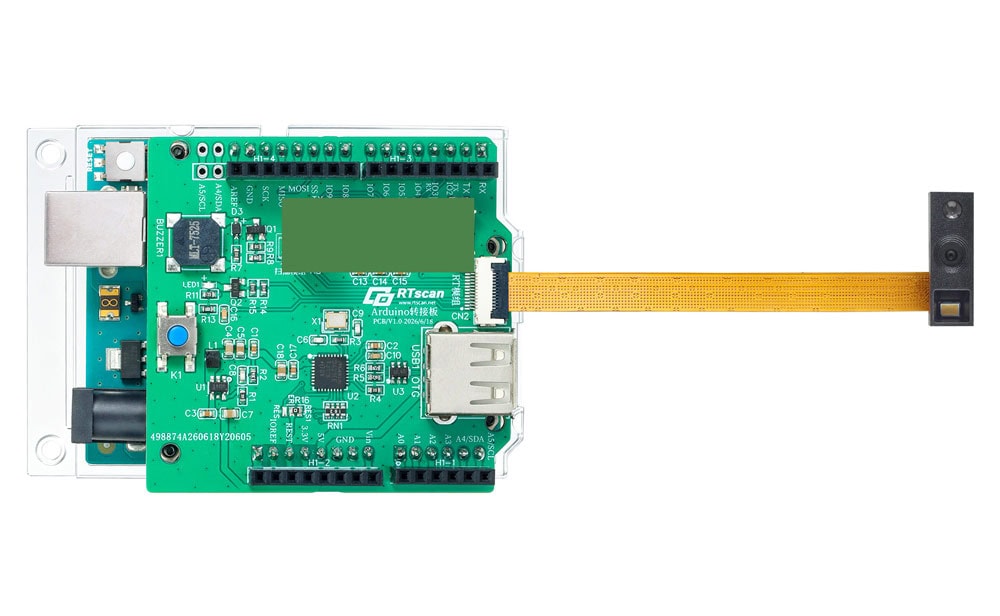
RTscan Arduino USB & TTL Host Shield:
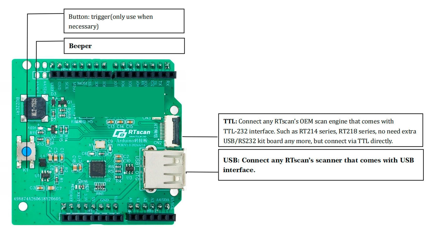
TTL-232 interface:
Thanks to the built-in TTL-232 interface, a beeper, and a trigger button, this Arduino host shield makes it achievable for our customers to use a small barcode scan engine directly with Arduino:
Connect the OEM barcode scan engine directly to this host shield via the TTL-232 interface; there is no need to use an extra USB Kit board anymore. This not only saves cost but also saves space for our customers.
You can use this solution with any of RTscan’s OEM barcode scanner engines.
USB Port:
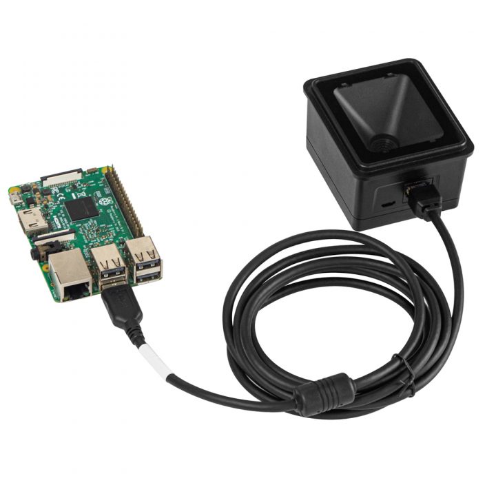
This Arduino host shield also has a built-in standard USB-A connector for direct connections of any RTscan scanners with a native USB interface. So you can also use any RTscan’s USB barcode scanners with this host shield.
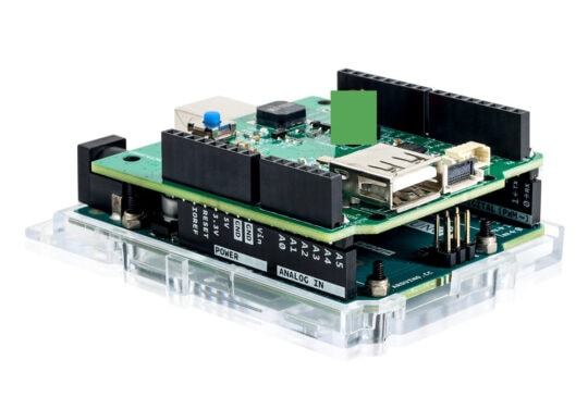
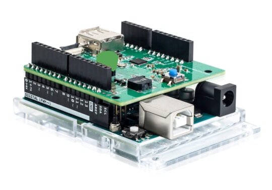
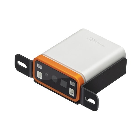
If you prefer to use a small OEM barcode scanner module with an Arduino board, then you can combine them simply as image below:
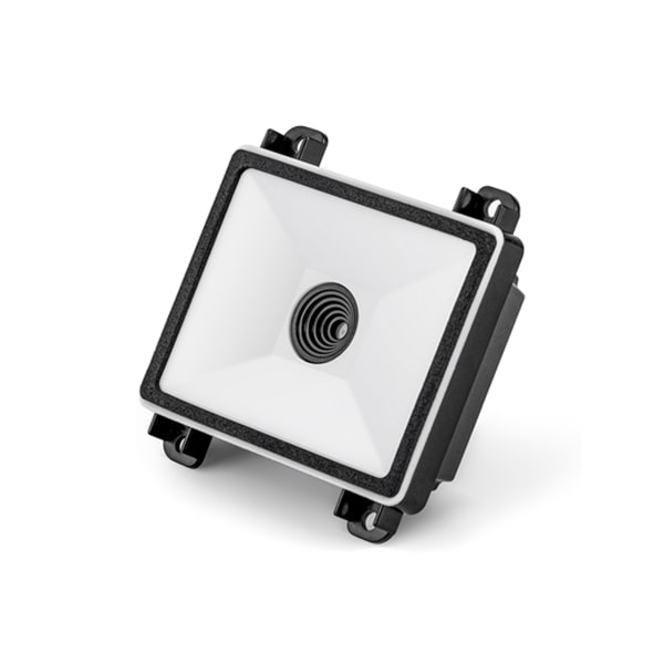
♠ All RTscan’s OEM Scanner Modules that are compliant with this solution:
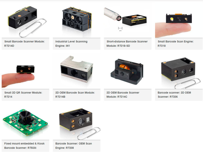
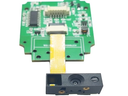
The above-mentioned TTL‑232 interface uses an FPC flat cable, but a usual flat cable can’t be longer than 30 cm to ensure proper communication. So if a 30‑cm cable is not long enough for your application, you can use RTscan’s USB kit board and connect the scanner to the Arduino host via the USB interface. 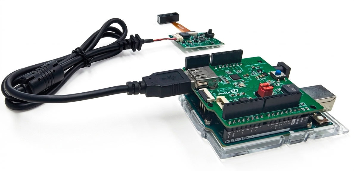
♠ All RTscan’s “OEM scanner modules + USB kit board” are compliant with this solution.
Step 1: Connect the RT214 + EVK board to the Arduino Uno as shown in Solution 1.
Step 2: Configure the RT214 to TTL-232 mode (9600 baud, 8-N-1) by scanning the setup barcodes below:
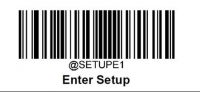
Enter setup
Set to TTL-232 mode

For more details, please refer to “RT214_User_Guide”
Step 3: Upload the following optimized sample code (rt214_uart_demo.ino) to your Arduino:
Here, we still take RT214 as an example to show how to make a USB barcode scanner to work with Arduino via USB-CDC interface:
Step 1: Connect the scanner to the Arduino USB Host Shield.
Step 2: Scan the configuration barcode to set the scanner to USB-CDC mode.
Enter setup
Set to USB-CDC mode:
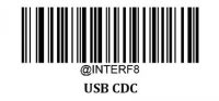
Recognized as a COM port device on the computer:
![]()
Step 3: Install the standard USB_Host_Shield_2.0 library via the Arduino Library Manager.
Step 4: Run the acm_terminal.ino example snippet provided by RTscan to capture barcodes instantly at 115200 baud rate.
In USB-HID mode, the scanner mimics a hardware keyboard, converting decoded barcode data directly into ASCII keyboard inputs.
Step 1: Hardware connection
Connect the RT214 scanner to the USB port of the Arduino USB host shield through a USB data cable.
Step 2: RT214 settings
RT214 set to USB CDC mode, scan the following Setting bar code
Enter setup:
Set to USB-HID mode:
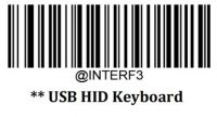
Recognized as HID keyboad Device on the computer:
![]()
Step 3: Include the library
Arduino Library Manager
First, install Arduino IDE version 1.6.2 or newer, then simply use the Arduino Library Manager to install the library.
Please see the following page for instructions:
http://www.arduino.cc/en/Guide/Libraries#toc3
Manual installation
First download the library by clicking on the following link:
https://github.com/felis/USB_Host_Shield_2.0
Then uncompress the zip folder and rename the directory to “USB_Host_Shield_20”, as any special characters are not supported by the Arduino IDE.
Now open up the Arduino IDE and open “File>Preferences”. There you will see the location of your sketchbook. Open that directory and create a directory called “libraries” inside that directory. Now move the “USB_Host_Shield_20” directory to the “libraries” directory.
The final structure should look like this:
- Arduino/
- libraries/
- USB_Host_Shield_20/
- libraries/
Now quit the Arduino IDE and reopen it.
Now you should be able to open all the examples codes by navigating to “File>Examples>USB_Host_Shield_20” and then selecting the example you would like to open.
For more information please visit the following sites:
http://arduino.cc/en/Guide/Libraries
https://learn.adafruit.com/adafruit-all-about-arduino-libraries-install-use.
Step 4: Run the sample code
Run: Scanner_USBHIDUniversalKbd. ino