If you are using Raspberry Pi microcontroller / single-board computer to develop your system, and at the same time, you need a 1d/ 2d embedded barcode scanner to work with it, then this article would be helpful for you:
Here we introduce how we connect the Raspberry Pi 3 Model B+ micro-controller with RTscan embedded barcode scanner and how to make them work with each other.
When we try to integrate an embedded barcode scanner with the Raspberry Pi microcontroller board, but we would meet these problems:
- How can we connect the embedded barcode scanner with the Raspberry Pi board together?
- When we choose an embedded barcode scanner, how can we control the barcode scanner by Raspberry Pi, meanwhile, how to upload decoded data to the Raspberry Pi system?
Read below and find how RTscan provides solutions for above questions.
Contents
Part I: Introduction of Raspberry Pi 3 model B+ and RTscan embedded barcode scanner
Part II: Connection solutions
- Solution 1: Connect via Dupont interface
- Solution 2: Connect via USB interface
Part III: Python Sample code/ Make the embedded barcode scanner work with Raspberry Pi system:
- TTL-232 Communication& Python Sample code
- USB CDC Communication
- USB-HID
Part VI: Video Demo
Part I: Introduction of Raspberry Pi 3 model B+ and RTscan embedded barcode scanners
Raspberry Pi 3B+:
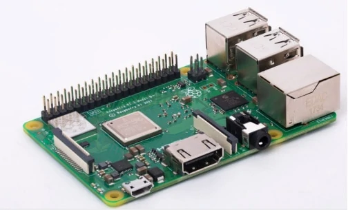
Raspberry Pi 3 Model B is the latest iteration of the most popular single-board computer. It provides a quad-core 64-bit ARM Cortex-A53 CPU running at 1.2GHz, four USB 2.0 ports, wired and wireless networking, HDMI and composite video output, and a 40-pin GPIO connector for physical interfacing projects.
Raspberry Pi 3 Pinout
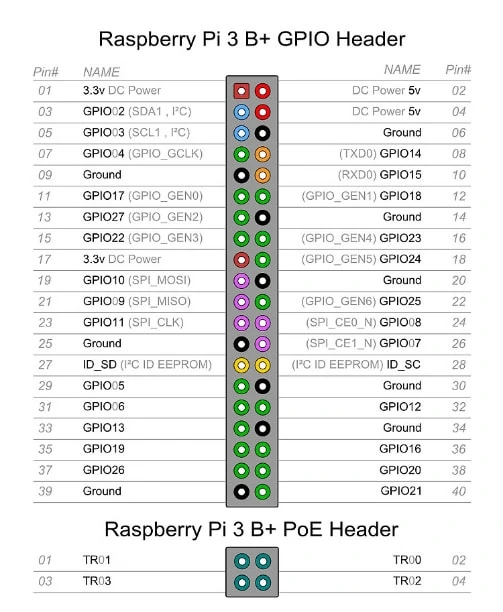
And for our application to connect with embedded barcode scanners, we need the 3.3V (or the 5.0v) power supply pin, and GND pin, RXD, TXD pins.
And also, we will demo how to connect our embedded barcode scanners: with raspberry Pi via USB interface.
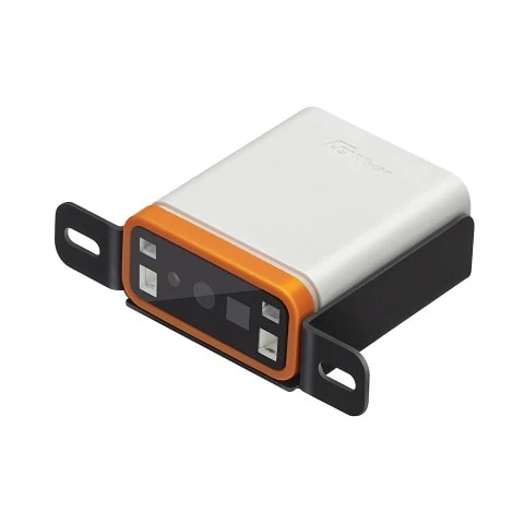
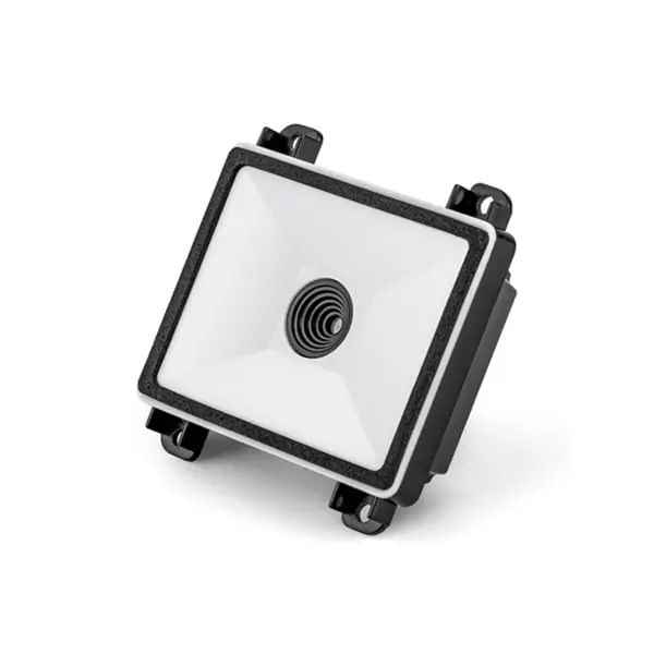
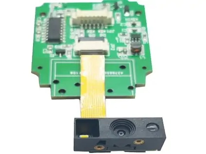
RTscan embedded barcode scanners:
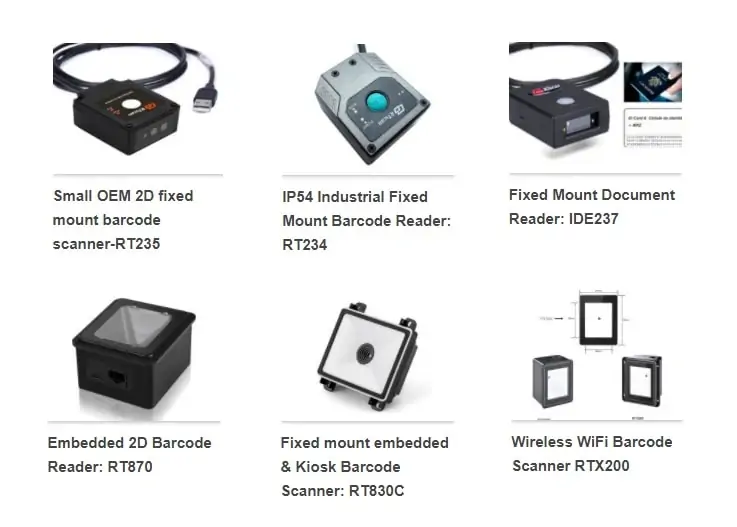
In this article, we just choose RT870 as an example to do the connection and integration, all the above listed models like RT830C, RT234 and RT231 etc are also ideal for connection with Raspberry Pi for different applications.
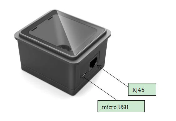
RT870 has RJ45 and micro USB output.
Part II: Connection solutions:
RTscan provides two types of solutions:
- Solution1: Dupont interface
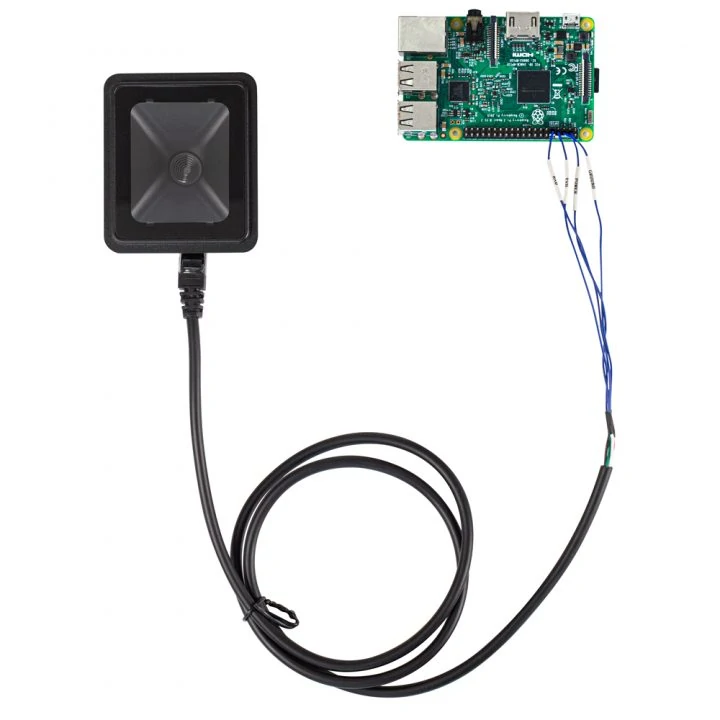
RTscan provides the following DuPont interface to connect the embedded barcode scanner with Raspberry Pi:
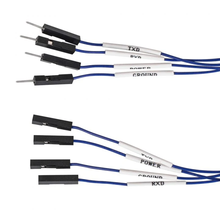
This is a simple solution, just connect the 5.0V power supply (the EVK needs 5.0v power supply), GND, RX, and TX pins.

RT870 RJ45 Pinout
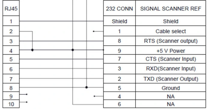
PIN Connection:
| RT870 | Raspberry Pi 3B+ |
| Pin4 VDD | 5V(Pin2 / Pin4) |
| Pin8 GND | GND(Pin6) |
| Pin6 RX | Tx(Pin8) |
| Pin7 TX | Rx(Pin10) |
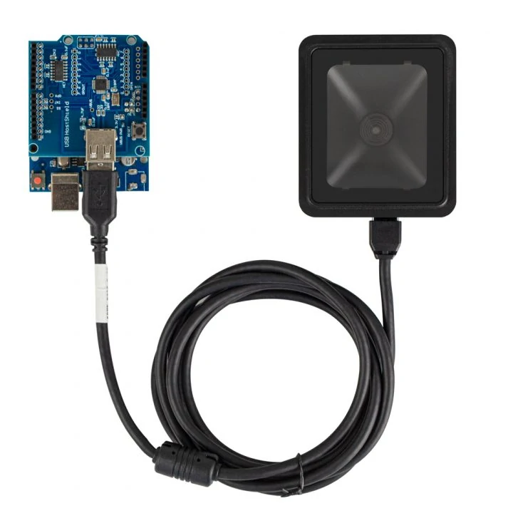
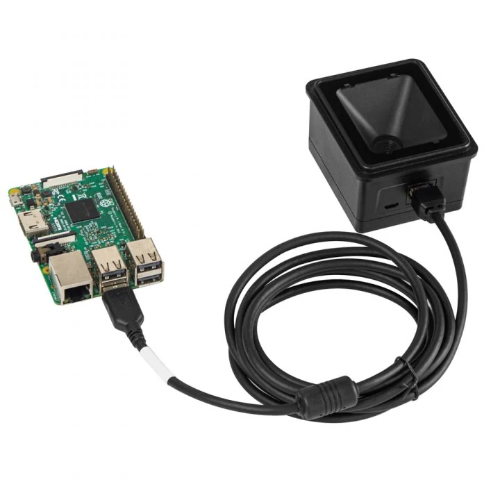
Solution 2: Connect via USB interface
For Raspberry Pi, if you prefer to connect the embedded barcode scanner via USB interface, it also is fine, setup RTscan’s barcode scanner to HID mode (work directly) or USB CDC/Virtual Com mode (follow Part III/USB CDC communication).
Part III: Python Sample code/ Make the embedded barcode scanner work with Raspberry Pi system:
We developed Python sample code to work with our scanners so that you can copy our source codes and program your system very quickly and no need to write the whole code one by one; save your time and speed up your integration work!
In this article, we choose the RT870 as an example to do the programming. Below we show how they work together when they connect via TTL-232, USB-CDC, and USB-HID.
TTL-232 Communication& Python Sample Code
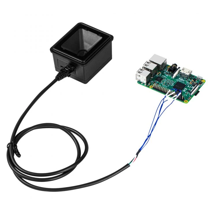
Step 1: Hardware connection
Connect the 5.0v power supply pin, and GND pin, RXD, TXD pins via Dupont cable.
| Raspberry | RT870 |
| TX(GPIO14)(PIN8) | RX |
| RX(GPIO15)(PIN10) | TX |
| 5V | POWER |
| GND | GROUND |
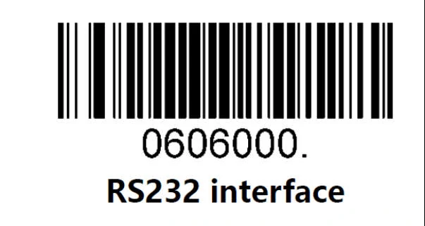
Step 2: RT870 settings
RT870 needs to be set up with RS232 mode, scan the following barcode
Set to RS232 Mode, the default baud rate is 115200, 8-n-1
For more details, please refer to «User-Manual-RT830A-RT870-RT860_V1.2.3»
Step 3: Raspberry Pi Settings
Use serial port 0 in Raspberry Pi,
/dev/ttyS0
More settings would be required to enable Raspberry Pi serial0, please see below (If you already opened it, then ignore this):
1.Enable serial port ttyS0
Open the serial port/dev/ttyS0
Via command window, input:
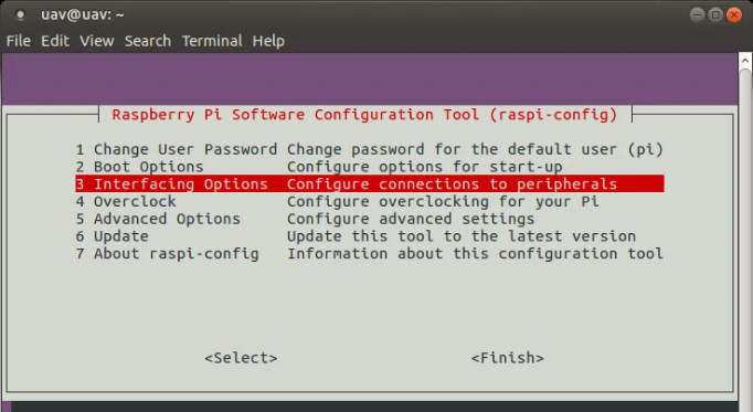
sudo rasp-config
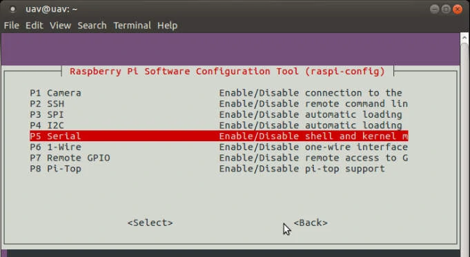
2.Open the system configuration interface as shown below, select Interfacing Options
Then select serial:
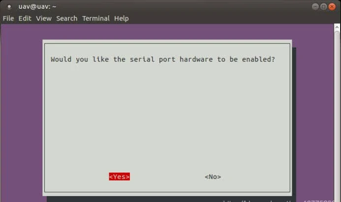
Select No:

Choose Yes:
Finally, save and exit.
Now, please enter the following command, check the serial port ttyS0:
ls -la /dev/
But, if it still cannot be used, please double-check and re-configure it.
3. Close the Console
In the terminal, input:
sudo systemctl stop serial-getty@ttyS0.service
sudo systemctl disable serial-getty@ttyS0.service
Then, restart
And input:
sudo systemctl mask serial-getty@ttyS0.service
Now it works!
4. Modify Raspberry Pi CPU frequency (optional, you would no need to do this)
After the above steps 1 and 2, the settings are theoretically completed. But some times:
(1)After sending a string via serial port, in most cases the receiver shows up garbled data.
(2) When the serial port receives data, if it appear data like: **\xe8 \xe9**
This would be caused by the wrong working frequency of the Raspberry Pi, information link:
Raspberry Pi 3 login via UART on GPIO Baud Rates broken
The modification method is described as below:
sudo vim /boot/config.txt
Find out whether the sentence core_freq=250 is enabled. If not, remove the # number in front of this sentence, or add core_freq=250 at the boot/config.txt, done.
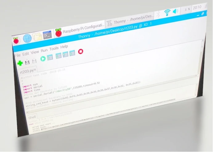
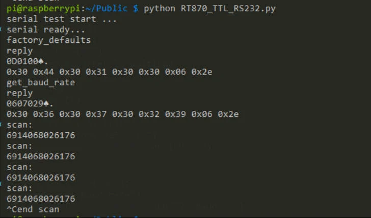
Step 4: Run the Python sample code
Run: RT870_TTL_RS232.py
And the RT870 automatically detects and reads bar code.
Output:
Introduction of commands protocol for RT870
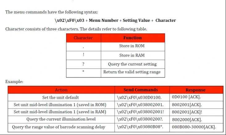
Example:
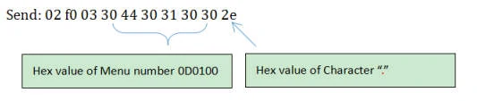
Response: 30 44 30 31 30 30 06 2e
For more details, please refer to 《Programming_Commands_Guide(RT203-RT830).pdf》
USB CDC Communication
If we want to use the USB port and make it work as a virtual serial port, set up the RT870 to USB Com port emulation mode. And the RT870 scanner will be detected as a COM device in Raspberry Pi.
Step 1: Hardware connection
Connect RT870 to the USB port of Raspberry Pi through a data cable
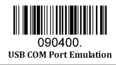
Step 2: RT870 Settings
RT870 set to USB CDC mode, please scan the following Setting bar code
Set to USB output
Set to USB CDC mode
Step 3: Raspberry Pi Settings
The RT870 USB CDC mode is the USB Com port emulation mode, the device name usually is:
/dev/ttyACM0
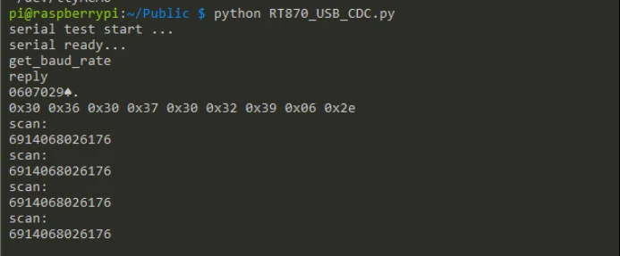
Step 4: Run the Python sample code
Run: python RT870_USB_CDC.py
Output:
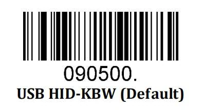
USB-HID
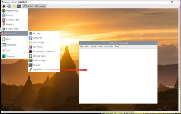
If you prefer to connect the embedded barcode scanner via USB Keyboard simulation, it also is fine, setup RTscan’s barcode scanner to HID mode:
Then open “Text editor” from Raspberry Pi software, now run the bar code scanning, the decoded data will show up directly.
The above python sample code can be used for other embedded barcode scanners, e.g: RT830B. But we can provide sample code for most of our embedded scanners, if you want to learn more about them, please view the links below:
Part VI: Video Demo
You can also refer to the following video demo, to see how the embedded barcode scanner work with Raspberry Pi: